In 2008 I took a QUAD 303 and 33 pre-amp as part exchange against some work on a QUAD 405 which was to be modified with my DCD–Mod3 PCBs and with an input gain control for use in a studio ~ The QUAD 303 I was told was originally “from the BBC” and was a 303A2 which was a BBC modified version for driving the LS3/8 loudspeaker and should have been fitted with an active crossover in a tray under the amplifier base.
The amplifier arrived and did not have the crossover fitted and it had been modified with 4mm speaker sockets whereas the 303A2 output would have been on a 5 pin “XLR” connector which was still fitted ~ I like the 303 and because the 303 A2 has a handle fitted to the top I thought it would make an excellent general purpose “Lab Amp” especially when fitted with a “volume” control.
When I say a “Lab Amp” I mean a general purpose audio power amplifier that can easily be put into service at short notice to test other equipment and one which does not take up too much shelf space or require careful handling and has predictable and repeatable performance ~ The 303 has a capacitor coupled output which also makes it safe for connecting to customers speakers in unknown systems and the addition of an input gain control would enable direct connection to CD players etc.
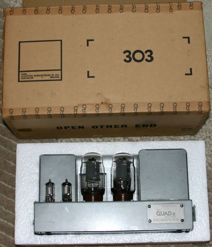
The QUAD 303 was not QUADs first transistor amplifier ~ The QUAD 50 was a push pull transistor design with a multi tapped output transformer aimed at professional users due to its high cost and odd connections ~ An interesting point about the QUAD50 and the QUAD 303 is that they were intentionally made the same size as the QUAD II valve amplifier and also had their input and output connections at one end.
Having all the connections grouped at one end the QUAD II QUAD50 and QUAD 303 could easily replace each other in professional fixed installations ~ It also saved on packing boxes with later QUAD IIs being shipped in QUAD 303 boxes with polystyrene inserts but more importantly to me it would make the QUAD 303 based “Lab Amp” easier to operate with all the connections and volume control at one end.
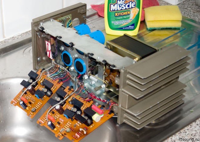
The QUAD 303 A2 was in reasonable condition and tested okay apart from a damaged fuse holder ~ but as usual the PCBs fitted in base had collected layers of dust and dirt over the years.
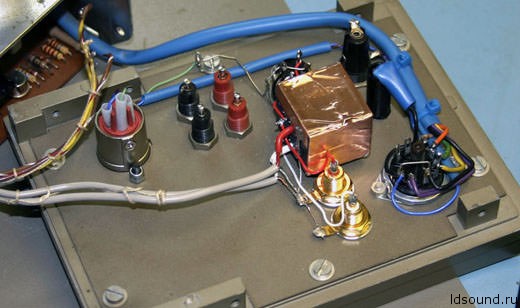
The easiest way to clean the PCBs in situ is to hinge them down and wash them over a sink making sure not to wet the transformer ~ I use a hard spray of Mr Muscle kitchen cleaner as seen in the picture followed by hot but not boiling water and then I dry the PCBs with ~ a hair dryer.
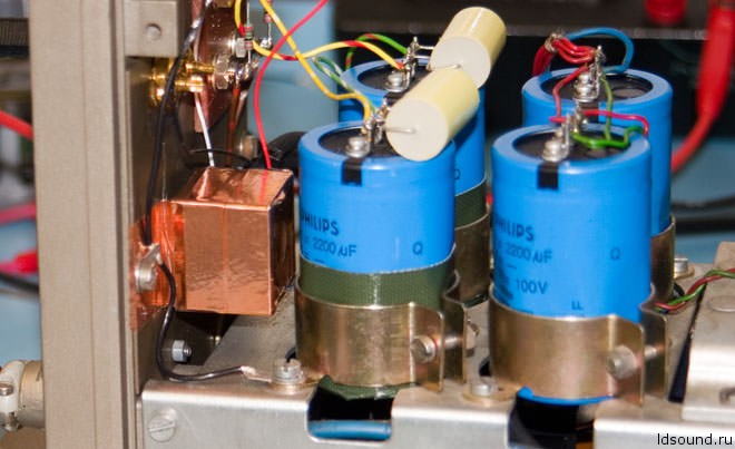
QUAD303 A2 New 4mm output posts and gold phono connectors – link to Capacitor Soakage The 4mm connectors that had been fitted were cheap socket types which were replaced with Binding posts.
The internal wiring to the output sockets was made direct from the output capacitors as shown and the resistors R1L and R1R were moved to the sockets which were mounted on a 5mm plastic panel at the front so the side “binding” holes cleared the front casework.
Extra 4,7 µF poly caps were fitted across C1L and C1R:

Apart from replacing the 0,68 µF electrolytic input capacitors C100 with the orange 1 µF BC polypropylene ones and fitting an additional 4,7 µF capacitor across the regulator output no other changes were made ~ I did look at increasing the input impedance by making R101 larger so that a 50 kΩ pot could be used for the input gain control but this would worsen the signal to noise ratio for low gain settings so I investigated the effect of loading a 10 kΩ log pot with the 22 kΩ of the QUAD 303 input impedance
I had some 10 kΩ ALPS 27 mm stereo log pots with 41 detent positions which measured …
| Position | Load 1 MΩ | Load 22 KΩ | Difference | +3 kΩ | Difference |
| 10
9 8 7 6 5 4 3 2 1 0.5 0 |
0dB
–1 –3.7 –7.8 –12.8 –16.6 –22.2 –29.8 –38.9 –53.9 –70 –99 |
0 dB
–1.4 –4.6 –8.7 –13.8 –17.2 –22.5 –29.8 –39 –54 –70 –99 |
0 dB
–0.4 dB –0.9 dB –0.9 dB –1 dB –0.6 dB –0.3 dB 0 dB –0.1 dB –0.1 dB 0 dB 0 dB |
0dB
–1.1 –3.8 –7.6 –12.5 –16 –21.8 –28.6 –37.6 –52.6 –69 –99 |
0 dB
–0.1 dB –0.1 dB –0.2 dB +0.3 dB +0.6 dB +0.4 dB +1.2 dB +1.3 dB +1.3 dB +1 dB 0 dB |
The rotation is from 0 which is fully anticlockwise with each step being 4 “clicks” or detents with the first 2 detents recorded as 0,5 ~ Note the log law of the ALPS pots is made from 4 linear sections with differing slopes as almost all log potentiometers are ~ The column ‘Load 1 MΩ’ shows the intended law for the ALPS “Log A” type volume control.
Having never done this exercise before I was very surprised that the difference between the high 1 MΩ load and the low 22 kΩ load was was as little as 1 dB ~ The source impedance for these tests was 5 Ω output from an HP35670A so I checked the results with a higher source impedance by placing resistors in series with the AT 35670A generator.
Results from one of these test runs with a 3 kΩ resistor in series with the ‘top’ of the 10 kΩ pot are shown in table on the right ~ With a 10 kΩ potentiometer in parallel with the 22 kΩ QUAD 303 input impedance the load would be about 6,8 kΩ at maximum and 10kΩ at minimum and would move between these values as the volume is varied.
With 3kΩ in series the input impedance is about 10 kΩ at maximum and 13 kΩ at minimum and the gain variation is less dependant on the output impedance of the source device which ~ with the predictable detents ~ allows better subjective evaluation without measuring equipment so I fitted 3 kΩ series which did not affect the S/N ratio much.
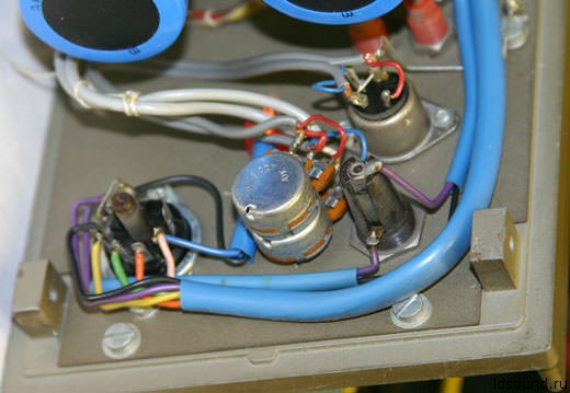
Testing the almost finished amplifier showed a difference between channels which was traced to the insulation on the output capacitor C1L being split so this was repaired with the green NATO grade silicone finish gaffer tape as shown.
This repair actually made the crosstalk worse because the isolated capacitor can was now capacitively coupling to the adjacent input pot and its wiring.
QUAD 303 A2 input pot with copper tape – Link to Capacitor Soakage:
ALPS stereo potentiometer:

ALPS 27 mm pots have screens between the sections which connect to the front metalwork but the case is made of blue plastic (not velvet) so the rear section especially is open to pick-up from adjacent signal sources like C1L here in the QUAD 303 or mains wiring in the QUAD 405 ~ A cure is to cover the case in 25 mm wide copper tape which is connected to ground to prevent the capacitive pick-up ~ Note the additional ground connections from the front panel to the main chassis ~ The un-shielded input wires from phonos to pot were run between the pot and front panel and did not show any signs of pick-up.
Testing the modified QUAD 303A2:
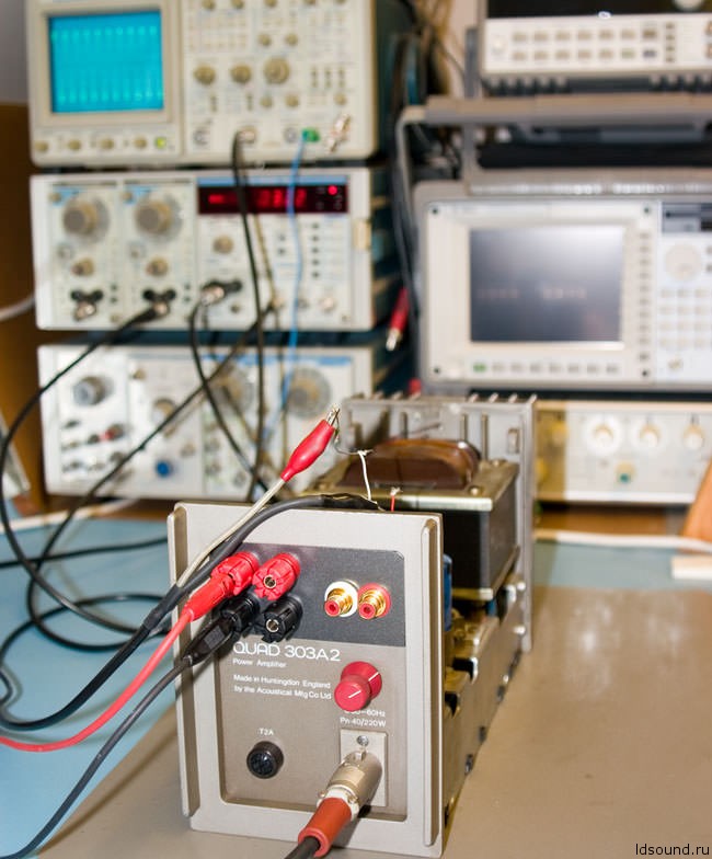
Testing the QUAD 303 A2 to determine the series input resistors for the gain pot.
The tables above were measured using an Agilent HP35670A ~ seen in the right background ~ which is very accurate for such relative tests.
Although its ultimate accuracy was not required here ~ being able to see multiple measurements for both channels at the same time is very useful.
Tests were also made with a Tektronix AA501 and SG505 as seen in the left background.
Having the outputs of the AA501 always displayed on a scope often helps reveal some odd or intermittent problems such as the insulation failure of C1L mentioned above.
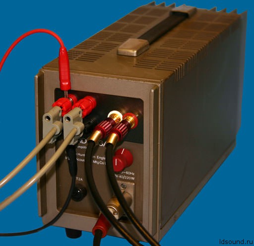
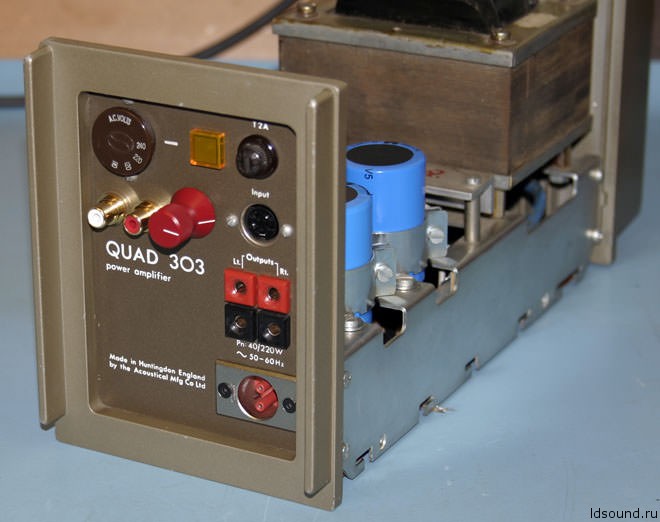
With the 4mm binding posts mounted on the 5mm plastic panel large diameter cables and 4mm plugs can also be fitted in the side of the binding posts as shown in the picture below ~ The panel also covers the large 5pin DIN hole where the phono sockets are now mounted.
The spacing between the output posts was made the ‘standard’ 3/4 inch or 19mm and although this is very close it enables ‘professional’ audio test leads to easily connect as shown.
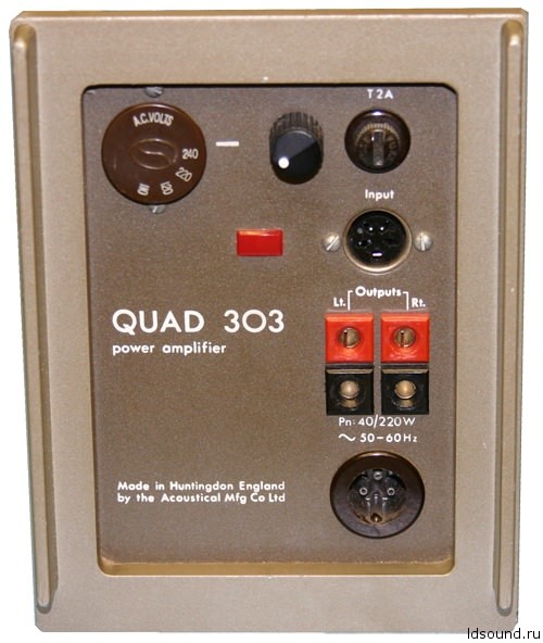
Note the mains input socket is the original LNE variant of the XLR connector reflecting the BBC heritage of the QUAD 303–A2 and the red knob on the gain control is from a 1970s BBC control panel so looks like it belongs where it is
The finished modified QUAD 303A2:
~ QUAD 303 Volume Control mod ~
On the left is a standard QUAD 303 which already had a volume control fitted by someone else ~ Note the small control knob between the voltage selector and the mains fuse ~ Not a good place for a signal connection.
I was asked to modify this amp ~ which was not working due to failure of the 1960s output capacitors and some previous bad PCB repairs.
The plan was to replace all the electrolytic capacitors ~ repair the fault and fit an ALPS 27 mm volume control in place of the 16mm one ~ The amp was for use in a small sound studio where the mains input would best be a BBC LNE type (as shown above) to fit the rest of the bay wiring.
First thing to do was to repair and test the QUAD 303 then clean it up ready for the new volume control.
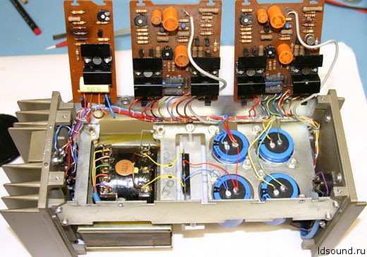
On the right the amplifier with new PSU and output capacitors fitted ~ The regulator and right amplifier board needed some new transistors ~ The 303 was then tested prior to changing the other capacitors or cleaning up the bad track repair to the left channel board.
As shown the amplifier tested to spec and the boards were un-soldered and removed to clean them and replace capacitors and tidy up the wiring loom damaged from several previous repairs ~ After replacing the reworked boards it was found that the bias and offset pots also needed changing because their setting was not stable when adjusting and there were some dead spots around the ideal settings.
On the back of the front panel the “original” volume control nested between the mains selector the neon indicator and the fuse (A bad position for electrical safety).
The DIN input is close to the mains wiring and even without a volume control can pick–up mains hum ~ but when driven from the low source impedance of a good pre–amp this is not audible.
The volume as originally fitted was known to pick–up audible mains noise ~ mainly from the neon indicator ~ It was this problem and seeing my screened ALPS pot that lead the owner to have this amplifier modified.
The new 27 mm 20 kΩ log pot fitted where the neon indicator was ~ the rectangle slot for the neon was rounded out and a new neon fitted the round hole where the old pot had been ~ Rather than rewire the new neon I removed the neon and resistor and fitted the original into the case as shown ~ this made the overall length about 12mm less with no exposed connections.
New input phonos were wired parallel to the 4 pin DIN and the the LNE mains plug fitted nicely in place of the Bulgin plug.
The finished QUAD 303 with BBC control panel knob new ALPS volume control and phono input connectors ~ The original silver plated output connectors were not to be replaced but were cleaned.
There was no audible hum pick–up from this arrangement although the phono inputs are near the mains selector ~ If the phono connectors were mounted lower down they may pick–up crosstalk from the output capacitor cans and may need additional screening.
On materials: keith-snook.info
